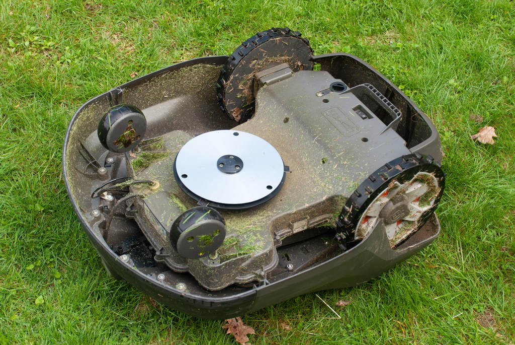
At a former employer, I worked on an lawn care robot that had some cooling issues. It had a stereo camera, and was running machine learning algorithms on-board to navigate around the user’s yard.
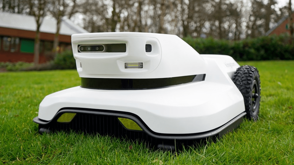
similar robot
The vision processing chip had only ever been used on indoor robots at this company, and I was tasked with making sure that it would work outside. From preliminary testing on summer days, the chip was overheating on 30C days, and our goal was for this robot to work in towns in Texas, where temps can reach 42C for days at a time. Solar radiation increases both the temperature of the air near ground level, where the robot operates, as well as inside the cavities of the robot, as heat is absorbed by any dark plastic.
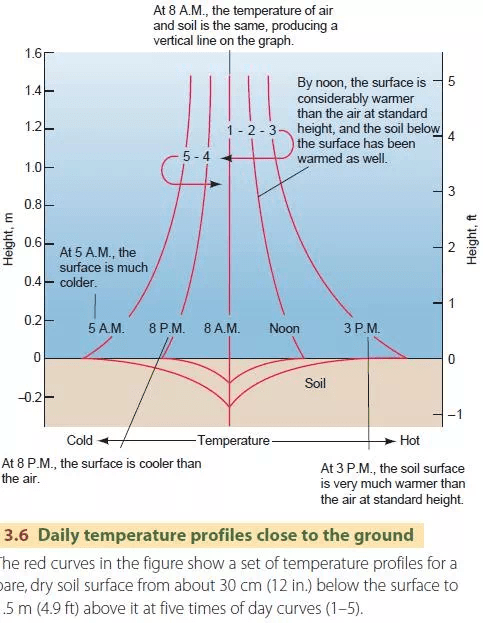
From our studies, we found that the air can be up to 12C hotter just above the ground at solar peak (<.5m) than the given “weather” temperature.
Additionally, we wanted to avoid using active cooling if possible, as a fan would be noisy and have an increased cost due to exposure to weather (IP Rating). Further complicating the situation was that the chip was designed for use in smartphones, meaning that it had very low thermal conductivity out the top of chip.
The types of passive cooling solutions that were available to me at a reasonable cost range fall into some combination of these categories:
- Venting via natural convection
- Needed to keep a pleasing industrial design, as well as prevent water ingress, so it was impossible to vent in the region of the chip.
- Thermal mass (essentially a volume of solid or liquid that could keep the temperature stable during the duration of the mission)
- weighs too much and will throw off the balance of the robot
- Heatsink
- Ineffective without adequate venting
- Passively circulating fluid system
- Showed promise due to the ability to pipe heat to other regions of the robot, where venting was easier.
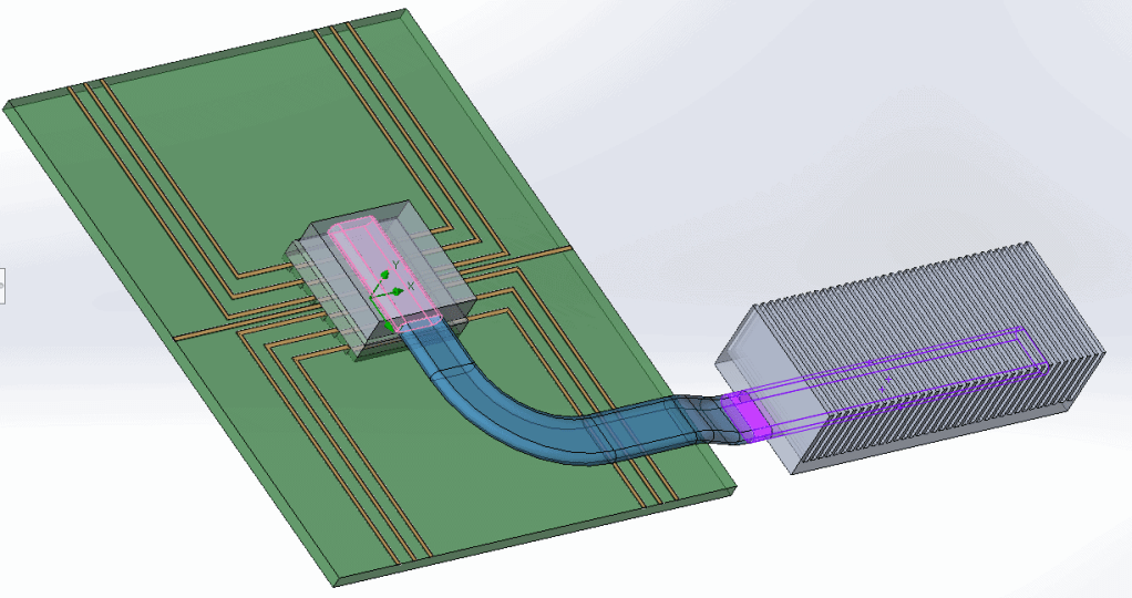
To determine if my solution was feasible, my team and I worked on a simulation before fabricating a prototype. Using Solidworks Flow Simulation, we developed a model that showed, in the worst case, that our solution was feasible.
It is difficult to estimate the thermal load that a chip will produce, given that it is impossible to know how efficient that algorithms running on the chip will be. However, most chip manufacturers offer use cases in the datasheet for each chip. For example, a Qualcomm phone chip might have the ability to run using all of its cores simultaneously for a CPU-heavy application like image processing for ML. I usually design for the maximum thermal output the chip could possibly have, as it prevents the possibility of a future software update breaking the system because the chip runs too hot.
Given the above constraints, I converged on a heat pipe system. Heat pipes are an awesome technology which saw first usage in spacecraft, that allows heat to move throughout a system without moving parts. They are perfect for distributing heat more evenly throughout a heatsink as well. Buy one and test it out yourself by putting one end into hot water, and see how quickly your hand feels the heat! They can achieve effective thermal conductivities many times that of copper.
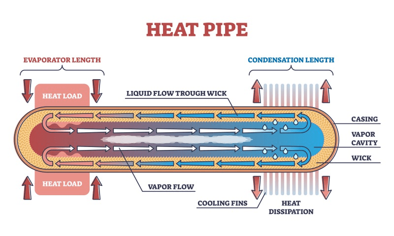
The heat pipes moved heat almost instantly from the center of the robot to cavities near the mower blades, where fresh air would replenish hot air.
I did calculations for the most effective fin spacing, so that the heat leaving the end of the heat pipe would dissipate quickly, preventing the temperature at the chip location from rising. The University of Waterloo has a lot of good tools for estimating the effectiveness of heat sinks. Here’s a link to the one I used to estimate the max temp that the chip would reach for a given fin spacing.
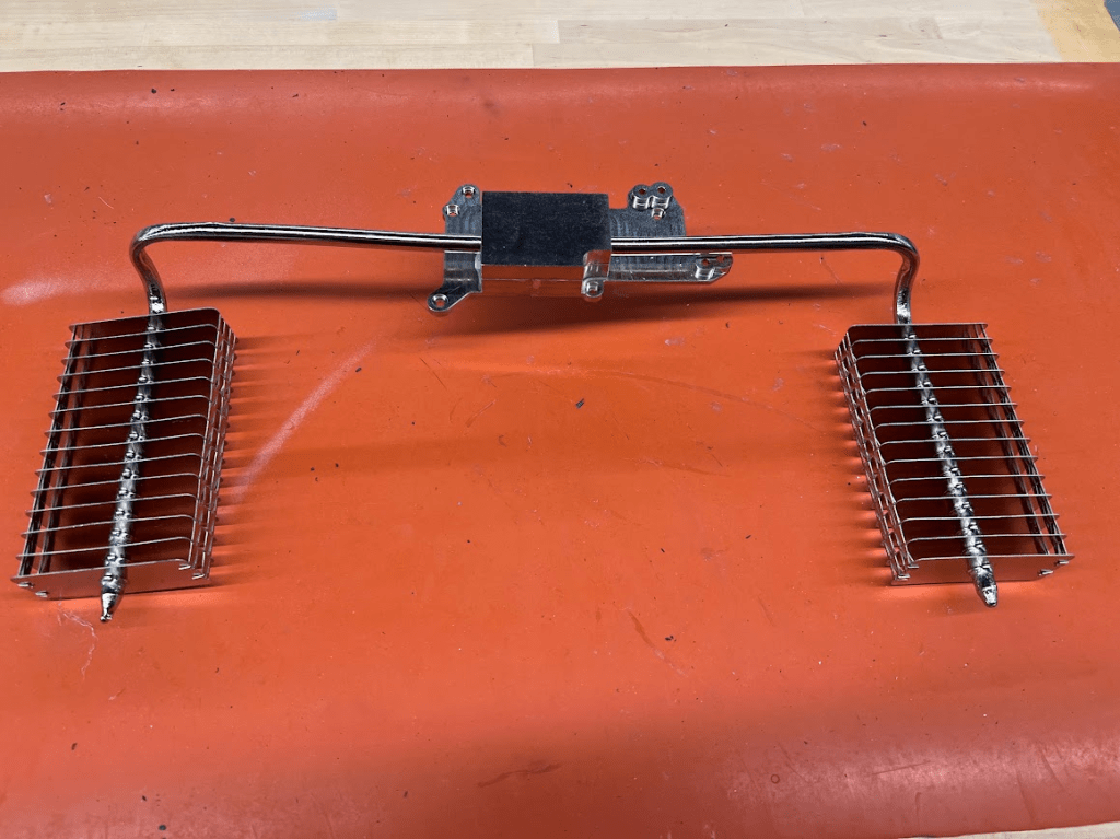
To prototype the design I had to bend a heat pipe and attach the fins in a way that would not add too much thermal resistance to the system. My first attempts proved out the concept, however, a professionally fabricated system performed significantly better!