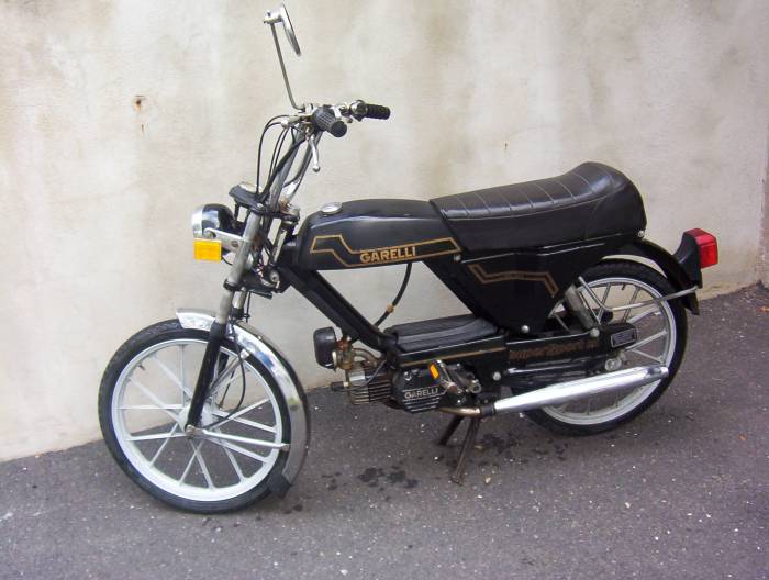
I mentioned in the description of this moped restoration debacle that it was initially supposed to be an electrical project. We were under that assumption until the first time one of us said, “As soon as we get the engine running, we’ll call it a day and convert it to an e-bike.” Now that we’re a couple quarantines into the project, I can say that it has become entirely about engine repair and metalworking. As the mechanical engineer in this duo, I can’t say I’m mad that it turned out this way. I had an ulterior motive of wanting to learn how to weld, and it looks like we’ll get the chance to try that out. We just bought a basic welding machine and want to convert the bike to something resembling a “cafe racer”, now that the engine works. The hallmark of this design is a long seat that goes across the frame of the bike. Since this bike was originally step-through, we’ll have to weld a bar across the gap that is there now, and attach the fuel tank and long seat.
Once the welder arrived and I unboxed it, I immediately realized how little I actually knew about welding. I’ve done it before in a guided workshop, but the boundaries of this project are much more ambiguous. What filament would we use? What type of steel should we buy? What dimensions? What is a reasonable price for a steel bar? What follows is an analysis of the strength of a long metal bar that would hold our weight, as well as an investigation into the strength we could expect from a novice weld job done with the cheapest welder we felt comfortable trusting our lives to. This analysis barely answered any of these questions. The bar is obviously going to be strong enough. As my roommate, Chris, said, “I probably could have told you that.” However, there are a few chapters left in my copy of Shigley’s Mechanical Engineering Textbook that don’t have coffee stains on it yet. I really wanted to get an understanding of how weld strengths are calculated in industry. So, here we go:
Beam in Bending Calcs

Using the properties of a tubular cross section, assuming we sit in the center of the seat and weigh roughly 200lbs, and ignoring the strange messages written on my board, we can see that we are in no danger of making the beam deflect, even if we use a beam as thin as 1.25″.
*I had to make an edit to this calculation when I realized that I had used the diameter of the tube instead of the radius of the tube when calculating the Moment of Inertia.
The final deflection for the .188″ thick, 1.75″ OD tubing came out to about .08mm. This very conservative estimate was just fine for a moped that will never go above 20mph and is only rated for riders up to 180lbs anyways. We would be a lot more careful and have this done professionally if it was being used on a motorcycle.
Weld Strength Calcs

Other Assumptions:
- We assume that the weld is only experiencing shear forces, even though it is also experiencing bending forces. This makes the calculation a bit more conservative, but also simpler. It allows us to represent the forces action on it as primary and secondary shear forces and get the magnitude.
- We are using Low-Carbon Steel as the “electrode” material, or the material that is deposited at the seam by the welder. This corresponds to a yield strength in Shigley’s:
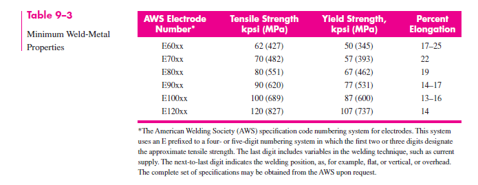
- The welder I have is a simple Flux-Core Arc Welder. I rent, and don’t have access to proper storage for explosive gases or 240V outlets. The welding material that came with it corresponds to the “E70xx” section of the welding properties table, but I assumed the lowest strength in the table since I am a beginner.
- Our design factor of safety is 2, mainly because we aren’t planning on taking this further than the end of the block at the moment.
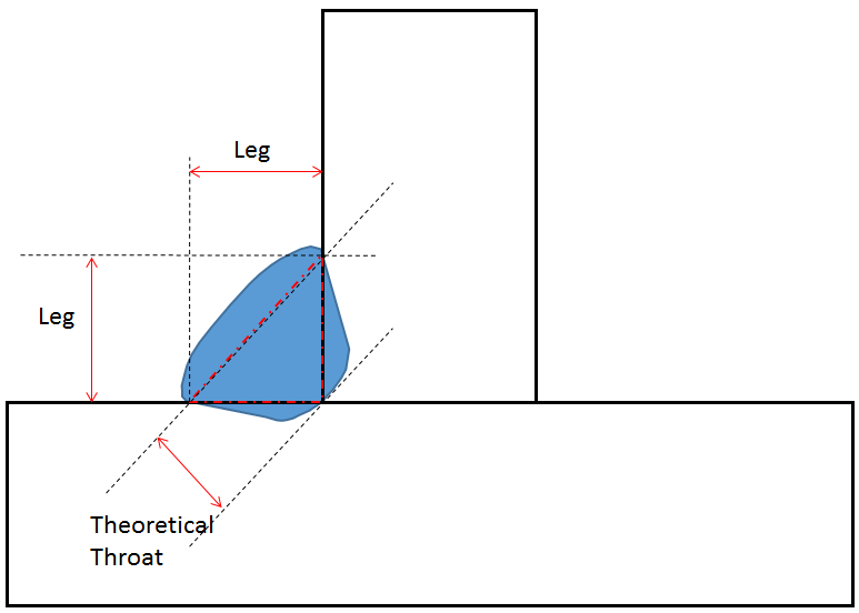
- I assumed that the “weld thickness”, or the horizontal leg in the below diagram, was 5mm. It will likely be larger when we actually put these pieces together, but I definitely see us messing up and blowing a hole in the metal somewhere.
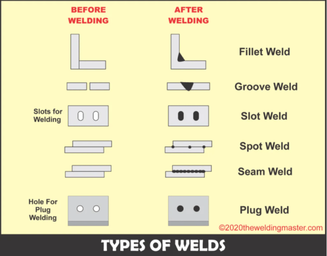
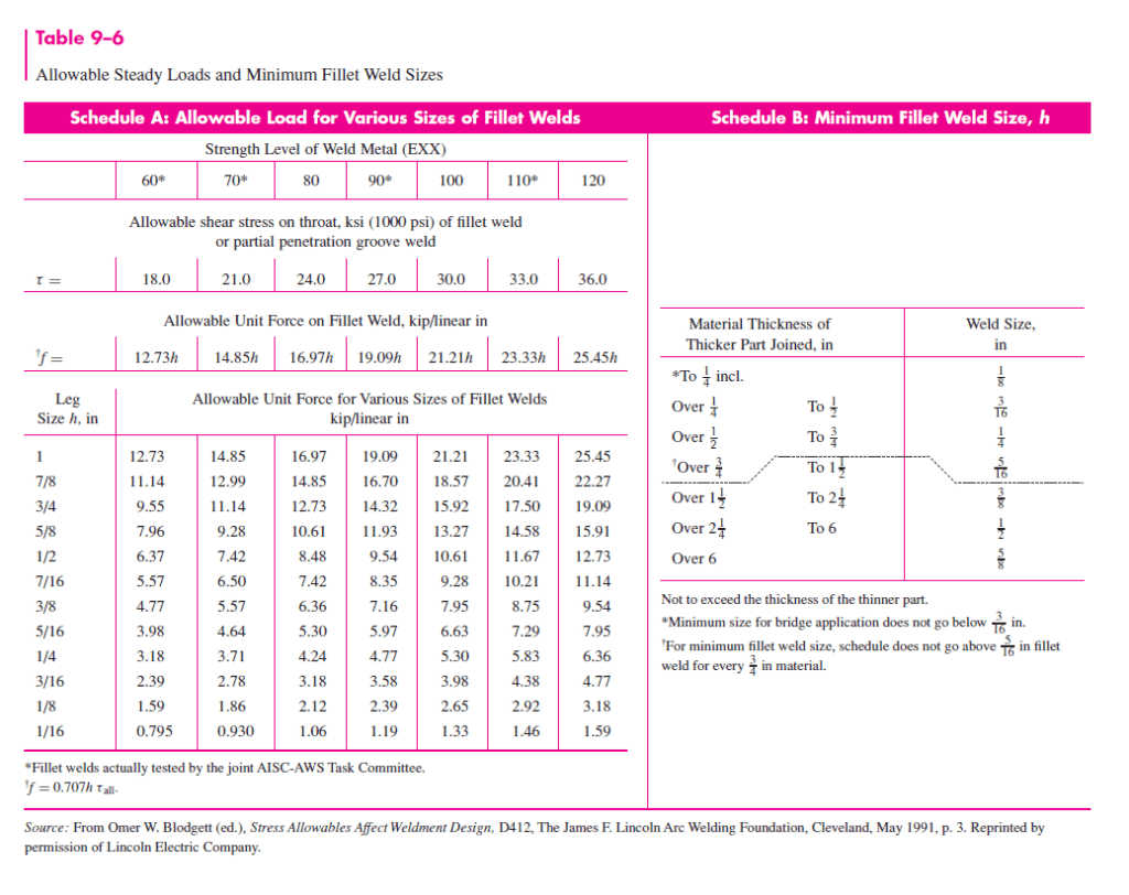
Using Chapter 9 from Shigley’s, I made use of the standard calculations they made for fillet welds in bending:
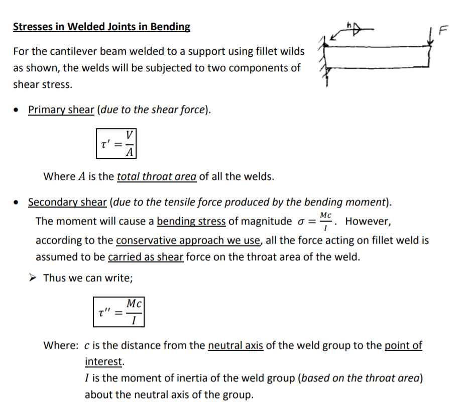
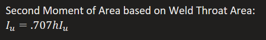
The moment of Inertia of the triangular fillet weld is the key part of this calculation:
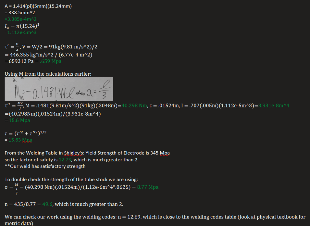
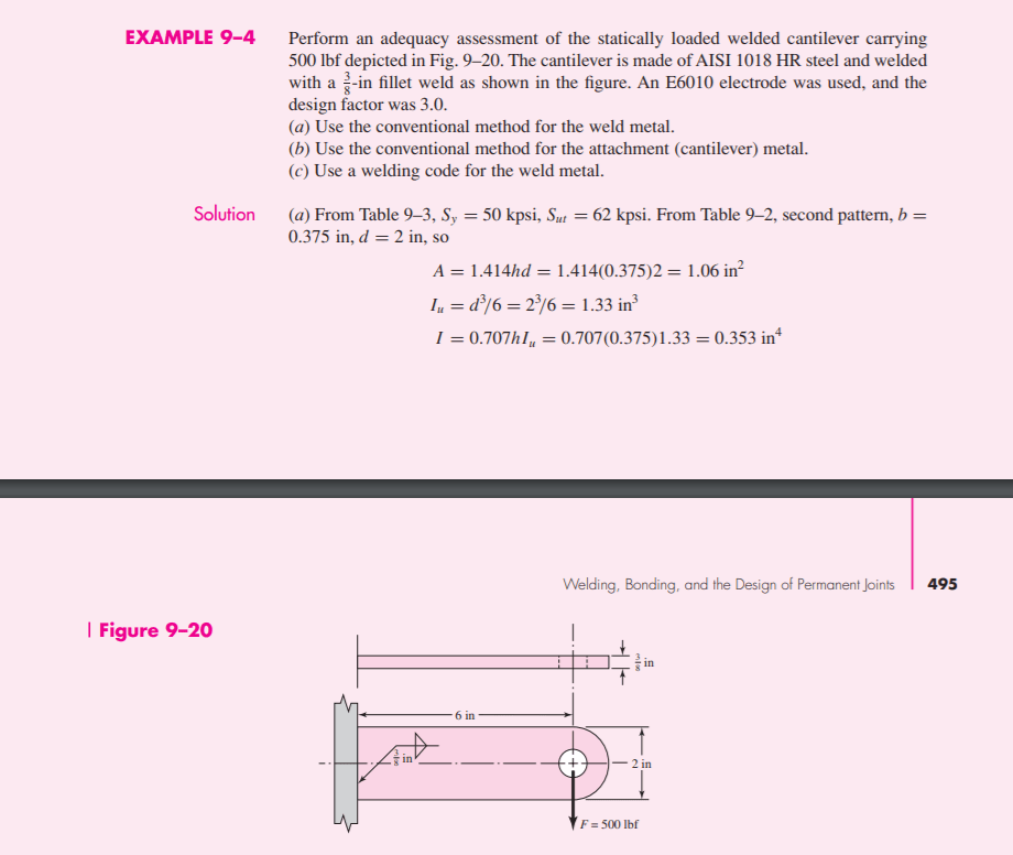
The final check of the weld strength involves this useful table from Shigley’s:
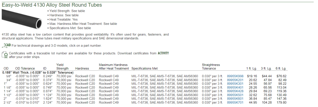
After spending a day making calculations for a part that a child could have told us was strong enough, we decided it was too expensive to get the thickness we wanted in the form of tube stock. We ended up going with a rectangular piece of metal that we could get for about a 3rd of the price listed here on McMaster. It is the same thickness (3/16″, .188in) and is easier to mount to, as we can drill holes in it for brackets to mount the seat and gas tank. Additionally, the cross section of the rectangular piece is slightly more favorable for resistance to deflection, although it doesn’t really matter for what we’re trying to do.
